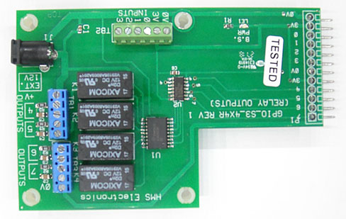


Formerly: GPIO-S3-4X4R
PH-4x4R, 4 Input (buttons) & 4 Relay I/O Board
Features:
There is a terminal block for inputs (normally open switches). These 4 inputs are labeled 0-3 and correspond to BTN0-BTN3 BrightSign inputs.
There are 4 relays to supply isolated outputs to remote devices or lamps.
The external 12Volts and 0Volts is provided on the terminal blocks so that
voltage can be supplied to external devices.
U.L. Single Contact Ratings: 12VDC/1.5A, 30VDC 1.0A, 100VDC/0.3A, 125VAC/0.5A,
240VAC 01.A Note: These are dual contact relays and the contacts are in
parallel. These relays can supply double the current rating of the single
contact rating. GPIO 4 through 7 going 'LOW' turns on the relays for
outputs 4 through 7. I.E. 3.0 AMPs @ 12VDC
When the BrightSign powers up is has pull-up resistors to the inputs (GPIO 0-7) which makes the signals high. As the BrightSign loads the software (which can take some time) this leaves the GPIO all high which would turn on the relays. This new design prevents this from happening. In the program, set the GPIO 4-7 to high and set to output. Then when you want a relay to turn on, set that GPIO low and the inverter chip inverts the signal to a high in order to drive the relay.
Note: Select a power supply with enough amps to handle your loads plus 100 milliamps for the board (all relays on).
Link: Schematic (See the schematic for typical load connections).
Author: Richard Harkey
Revised: August 27, 2024