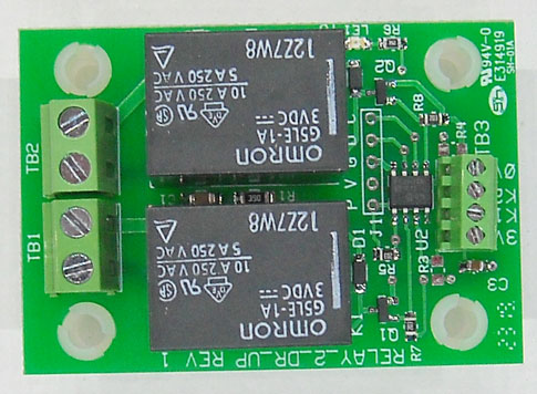

Isolated output (Relay2)

Relay2-DR-uP
Features:
The relay is used to supply isolated outputs (switch closures) to remote devices or lamps. U.L. Single Contact Ratings: 10 amps 120/240VAC
Because the BrightSign powers up with 3V on the GPIO (pull up resistors pull up the inputs to 3V). When BrightAuthor sets the GPIO pins to outputs (See: Presentation Properties), the outputs then go low. A microprocessor is used to solve this dilemma of not turning the relays on until the outputs go low. The microprocessor is also programmed to hold the relays off for 2 seconds after power is applied. This prevents a possible 'race condition' on power-up that could cause a pulse of the relay while the BrightSign boots. Set the GPIO outputs to high ('ON' in BrightAuthor) to activate the corresponding relay.
Note: Both GPIO control pins (K1 and K2 connections) have to be low (Off) before the processor will respond the the signal going high (ON)
Note: If driving a logic circuit using the relays, it may be necessary to disconnect the snubber network to prevent the snubber network from sending a pulse to the logic board when power is applied. I.E. with no BrightSign connections: If applying power to the contacts of the relay triggers (pulses) your logic circuitry, then open the connection between the capacitor and resistor of the snubber network (see the schematic for details).
Last Revised: 08/27/2024