USB-4RGB
for some BrightSign units w/USB
USB-4RGB

Features:
- 4 Sets of RGB drives (12 outputs)
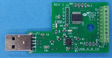
- footprint (3.5 x 3.5 inches)
- Terminal Block for 5 I/O's (programmable)
- On board LED's to indicate processor running.
- Branch Circuit Protection (Fuses) 4amps *1
Note: Branch circuit protection is set to 4 amps to match up with 24V LED
fixtures in order to meet safety requirements. For 12V LED fixtures, 6
amps versions can be ordered (Custom)
USB Setup: In BrightAuthor, select Presentation Properties, Serial Setup and
select port2. Set the port to 38,400, Ascii mode. The USB-Serial
Interface is handled by a Prolific USB-Serial converter and appears as a serial
port in BrightAuthor.
I/O's (TB1):
TB1 is programmable for 5 inputs or 5 Logic Level outputs:
- Mode = 0 : The 5 I/O's are programmed as outputs. The Brightsign
Controls the Outputs with CMD xx.
- Mode = 1: The 5 I/O's are programmed as inputs and are reported to the
BrightSign with input changes
- Mode = 2: The 5 I/O's are programmed as inputs and are used to select
scenes to play. Inputs need to be constant during play or play will halt.
- Mode = 3: The 5 I/O' are programmed as inputs and are used to select
scenes to play. Inputs are triggers and do not require no change of state.
- Link: Binary to decimal
info:
TB1 Mode = 1:
- Close the inputs to 0V (buttons/switches) to activate the inputs. The
inputs are reported as strings to the BrightSign and are evaluated as decimal
in BrightAuthor. I.E. Sending "1",13 causes a serial string event and
evaluates as 1 (not "1").
- When an input is released (goes back high by internal pull-up resistor)
an 8 is added to the string. I.E. "81",13 indicates input 1 was released.
This scheme allows the programmer to respond to inputs going high if needed.
Command modes:
Link: RGB Commands See this link for
the command structure to control the Drives!
Author: Richard Harkey
Revised: August 27, 2024