![]()
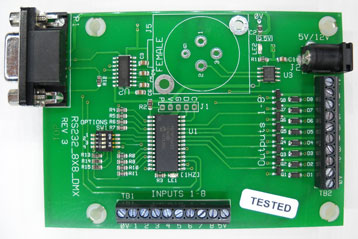
RS232-8X8
Features:
This board was designed with 'low impedance' drivers. The Proximity Sense boards run on 3.3 volts or 5V (available on the input terminal block). The V+ on the output terminal block is not utilized with AZ-Sense boards. The drivers can be used to drive 3.3 volts (logic levels) as well as 12-24 volt loads (requires a external 5-24V supply).
Rev 2.0 Firmware allows for multiple inputs low at the same time. I.E. If input 1 goes low ('1' is reported), then input 2 goes low (while input 1 is held low), then input 2 will be reported. If any 'active' Input (switch) opens then closes, it will be reported as a new input. I.E. suppose input1 is closed and input2 is closed and opened multiple times. A '2' will be sent with each successive switch closure. This logic is for all inputs. With Rev 2.x firmware, a single switch can be used to show closed and open. If you want to detect a door or drawer opening and then closing, arrange the switch to close when the door or drawer opens, and then the switch opens when the door or drawer is closed.
*********Output Control Commands (Lights):
Outputs: Connect Loads between 'Output' and +V.
Note: The brackets or the comma's are not part of the byte sequence.
Outputs are fade control enabled (dimming). Use this table of bits to determine the number to send from the BrightSign to control the outputs.
Connect Loads between 'Output' and '+V' on the output terminal block.
Note: A 'Fade' of zero, causes instant change in Brightness (no fade).
Note: Fade is the number of milliseconds to make a change in Brightness. A
fade value of 20 will take 20 milliseconds to change to the next Brightness.
So, to change from 0 to 255 (minimum to maximum Brightness) with Fade=20 (20
milliseconds per step of change) will take 20 * 255 or 5.1 seconds.
Note: The brackets are not part of the byte sequence.
Note: LED's are very responsive to PWM changes. A change from value of
1 (1/255 on time) to 2 (2/255) on time is 100% change is step. This is
very noticeable at very low PWM values. I recommend you start with a
brightness value of 10 then set the brightness with fade.
I.E. (CMD1, Output1, Brightness=10, Fade=0, 204) = 001, 001, 010, 000, 204
Then send a second Command 1 to adjust the brightness with fade (Brightness 128,
fade=040) = 001, 001, 128, 040, 204
Command1: To control any of the 1-8 Outputs (Command1), set the 'Select_Bits'
to match the outputs. Set the 'Fade' for those Outputs, Then set the
Brightness for those Outputs.
I.E. to turn on Output1+Output8 (to the maximum brightness=255, fade
rate=20), Command1=[1,129,255,20,204]
I.E. to turn off Output8 (brightness = 0, fade rate=20),
Command1=[1,128,20,0,204]
I.E. to Turn off Output1 (instant) (Select_Bits = 1, brightness = 0, Fade=0),
Command1 = [1,1,0,0,204]
With SW1-1 ON, the 'Not HMS Protocol is used. That is, a single byte controls the output.
Options (Option Switch 1)
| Note: External Supply Voltage: An External Power Supply is needed to power the loads on the output connector. Do not connect any loads that have their own power that exceeds the power as applied to the board using the 'Ext. Power Connector'. Doing so may result in damage to the board. I.E. Suppose that 12 volts is supplied to this board and you have a relay board with it's own power of 24Volts DC that powers the relays. The 24VDC will feed back into the board via the foldback diodes. Note: Foldback diodes are required for inductive loads such as relays or small motors. |
Updated: 03/02/2024